Rexarc is currently open from 7:30 AM – 4:00 PM EST, Monday – Friday. Read More
Rexarc is currently open from 7:30 AM – 4:00 PM EST, Monday – Friday. Read More
Pressure vessels have stringent design requirements to ensure they will operate safely under the specialized loads and stresses they experience. This technical report contains a detailed analysis of metal fatigue caused by cyclic loading and early indicators of fatigue in high pressure stainless steel vessels.
High pressure vessels were traditionally made of cast iron, but as technology advanced, ductile materials, often steel, became required by vessel regulations. Stainless steel grades are used at cryogenic temperatures down to -418°F, carbon steels are used for room temperature applications up to 750°F, and stainless steel grades are used at temperatures between 1100°F and 1650°F or higher.
The permissible pressure for any vessel is based on the operational temperature, environment, the fluids in contact with the vessel, and material choices, including the bolt and flange materials. The pressure is linked to the loads and stresses experienced by the vessel. These can include hoop and longitudinal stresses caused by internal pressure, cyclic loading, bending stresses, wind and seismic loads, tensile and compressive stresses, and thermal cyclic stresses.
It is also important to consider possible failure factors while designing a pressure vessel. Although stress theory predicts failures for brittle materials, it is not always accurate, especially for ductile alloys like stainless steel.
Applications of pressure vessels such as in industrial processing, storage and power generation are subjected to unusually high temperatures, pressure, and other harsh environmental conditions. These conditions require a special emphasis on different experimental and analytical methods to figure out how much cyclic loading these vessels can withstand while in operation.
Rapid developments in the space sector, chemical, and oil and gas industries require materials that can withstand extreme stress cycles, impact, high temperatures, and fatigue. Pressure vessels operating in these tough conditions are designed according to the guidelines laid by ASME. High localized cyclic and secondary stresses are taken into account by increasing safety factors and following design guidelines for all other specifications.
Life cycle analysis is one of the most complicated and integral aspects in developing a component that can operate at high temperatures under constant cyclic loading and stresses. Many research studies have estimated the life span for heavy-duty vessels and piping that operate under constant high temperatures and pressure. The piping and vessels usually fail due to fatigue initiated by cycling loading. No single technique can explain all fatigue mechanisms due to sheer complexity and the number of variables.
The vast majority of industries, including the oil and gas sector, frequently use cylindrical or tubular components as part of their engineering structures such as pipelines, boring and pressure vessels. These components are susceptible to collapse and failure under harsh operating conditions. Fatigue failure and cyclic loading must be considered while analyzing the modes of failure for pressure vessels and pipelines, which include crack initiation and propagation, and ultimate fracture. The two main decisive factors that impact the failure mechanism and crack propagation are the geometry and loading mechanisms of any vessel. Even a minor scratch on the surface of these vessels can act as a stress concentrator to crack propagation when the vessel is under cyclic loading.
Section VIII, Division 2 of the ASME Boiler and Pressure Vessel Code (ASME 2010) defines fatigue as “conditions leading to fracture under repeated or fluctuating stresses having a maximum value less than the tensile strength of the material.”
Pressure vessel material will undergo gradual, localized, and irreversible structural changes due to fatigue degradation.
The fatigue life of any pressure vessel is influenced by a variety of factors. The following factors affect and determine the fatigue life of pressure vessels; however, some factors have a bigger impact than others.
Metal fatigue starts with cyclic loading, leading to microscopic changes in the crystallite and grain structure of any given metal.
The amount of stress cycles during a lifecycle determines the fatigue the material will experience. The three primary stages of metal fatigue in response to constant cyclic loading are initiation, propagation, and rupture. With each stress cycle after the crack initiation, the crack grows at a very slow pace until the final failure. One example of fatigue caused by cyclic loading is repeatedly straightening and bending a metal wire around a spot until it breaks.
While designing and prototyping a stainless steel high pressure vessel, designers adhere closely to strict safety measures because of a variety of pressures and stresses combined with fatigue loads, cyclic loading, and seismic shock loads.
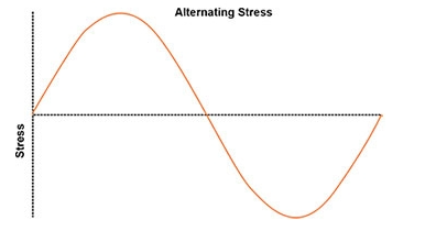
Before analyzing the fatigue life of a vessel, it is essential to know the fatigue life of the material, which is determined by the number of loading cycles at a particular stress level. Various similar samples are tested for any material until failure to estimate the fatigue life. A simple cyclic loading cycle is shown in figure 1. Testing materials are put under a lot of stress cycles, and failure happens suddenly.
Figure 1: A graphical representation of cyclic loading.
Vessel design starts with the selection of high-stress and fatigue-tolerant materials. The design includes features to significantly reduce vessel stresses. Transitions between geometric shapes are made as smooth as is feasible, round corners are preferred, and big radii are preferred over small radii.
While designing any pressure vessel, the user and final application define all of the operating circumstances, conditions and cyclic loading. The S-N cycle is made in accordance with the design data provided by the user, and a graph is created. The total amplitude of stress at any point is determined using the data of cyclic loading. The average stress over any solid section of a pressure vessel, bending stresses within the vessel, stresses due to defects and structural issues, thermal expansion and temperature related cyclic stresses, and stresses from designing such as notches are added to determine the stress range.
Equivalent stress is assigned to each set of specified loads in the load diagram. The number of cycles calculated using equivalent stress and loading cycles in S-N curve are compared. The final vessel design is feasible only if the number of allowable S-N curve cycles exceeds the maximum number of cycles from equivalent stress.
One stress cycle is considered complete as the inside pressure of the vessel increases from standard atmosphere pressure to operational requirements and then decreases to ambient pressure.
From the analysis of cyclic loading test data, the stress and the total number of cycles curve is created as seen in figure 2 (S-N curve). When developing S-N curves, the stress factor can be lowered by a factor of 2 or by 20 in the case of the number of cycles. S-N curve reduction factors consider environmental and size effects.
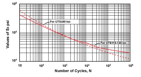
Figure 2: S-N curve used in designing the vessel.
Consider the straightforward scenario of a single variable load on a given pressure vessel for 30 cycles with a stress amplitude equivalent to 250,000 psi as shown in figure 3. The S-N curve shows that the design is suitable for the specified fatigue levels since 40 stress cycles lead to failure which is greater than the required number of cycles.
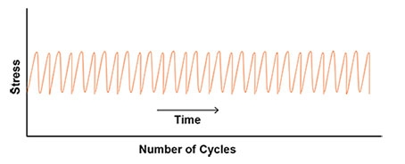
Figure 3: Variable loading diagram (S-N curve).
Various other pressure changes may be observed between pressure changes as shown in figure 4. It is necessary to determine the stresses brought on by these pressure variations and the total number of cycles. The difficulties in recording stress cycles get more difficult as the loads become more complex inside the vessel. To count these complex stress and loading cycles and integrate incomplete cycles to form complete loading cycles, one can use the rainflow counting algorithm or other similar techniques that adhere to ASTM E1049, Standard Practices for Cycle Counting in Fatigue and cyclic loading analysis.
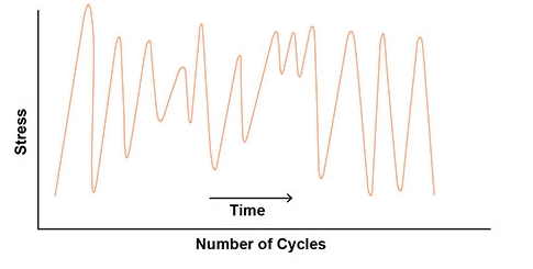
Figure 4: Complex and irregular loading cycles.
There are several stress and loading cycles, each with a variable number of cycles and stress levels. The cumulative effects of each stress and loading cycle on fatigue damage must be evaluated. The impact of stress cycles on the fatigue life of any vessel is assessed using Miner’s rule:
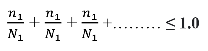
Where n1 shows the specified number of cycles at stress and loading of level 1, n2 shows the specified cycles for level 2, and so on. Similarly, N1 shows the permitted cycle at stress level 1 and so on. The vessel design is suitable only if the sum of all the ratios as explained earlier is lower than or equitable to 1.0 for any point. Other points and places in the vessel with significant stresses require repeating this process. The design of the vessel is accepted only when every point in the vessel complies with Miner’s rule.
Finding the early indicators in vessel material during maintenance requires non-destructive testing. Techniques used for non-destructive testing include radiography, liquid penetrant, magnetic particle approach, and ultrasonic.
A pressure vessel’s actual life may outlast its expected life. If operational vessel loads are lower than loads used during cyclic loading and fatigue analysis, the vessel will have increased actual life. If a vessel has more cyclic loads than estimated, the actual life may be less than expected. It is impossible to pinpoint an exact end-of-life time with high accuracy.
The interior and external surfaces of pressure vessels must be visually inspected periodically to look for scrapes, impact marks, signs of corrosion, wear, erosion, and fractures. Each issue should be assessed for its impact on the vessel’s fatigue life and cyclic loading. For instance, pitting corrosion is commonly observed in vessels, this can significantly increase local stresses leading to failure or a decrease in useful service life. When a vessel has exceeded 50% of its estimated life, it is a best practice to carefully inspect both its inner and outer surfaces using proper Non-Destructive Examination (NDE) techniques and visual inspection. Findings in this half-life examination are used to either proceed with daily operations or make necessary adjustments to the end-of-life estimates.
Not every component and part of a pressure vessel is under the same amount of stress. The most severely strained regions with high cyclic loading appear at points where the geometry changes, such as in nozzles and variations in diameter. Components with cracks and other defects can be replaced or repaired. To guarantee that the vessel life is increased beyond the estimated design life, fatigue and cyclic loading analysis of the replaced or repaired component is necessary. Of course, there is always a trade-off between the expense of replacing a vessel and the cost of inspection, maintenance, and analysis needed to increase the lifespan of the vessel.
Since last century, stainless steel is one of the most significant metallic products that are now on the market. Various stainless steel grades are divided into several AISI (American Iron and Steel Institute) classes. The stainless steel grades AISI 304 and AISI 316 are used in the construction of the great majority of stainless steel tanks and vessels. The choice of any material or stainless-steel grade for high pressure vessels is based on the rate of corrosion, cyclic loading, stress analysis and other severe operating conditions that can lead to hydrogen embrittlement and cracking due to stress cycles and corrosion. The data on cyclic loading, stress and corrosion rate aids in establishing the suitability of selected material based on extensive testing and analysis.
The goal is to select an affordable, reliable, and durable material that can last for a long time at an economical cost. Carbon or low alloy steel is added with thick layers of high alloy material through electrodeposition to ensure the requirements of high alloyed materials and stainless steel. The crystalline structure of stainless steel is used to categorize them, and the basic phase of austenitic stainless steel is austenite. The austenitic stainless steel 300 series is regarded as the most widely used material for high pressure vessels given the high resistance of a material to corrosion, cyclic loading, and harsh operating conditions.
The difference between carbon steel and stainless steel is the addition of chromium. All steel grades react with oxygen in any environment; however, this reaction happens very slowly due to chromium addition. Therefore, stainless steel becomes incredibly robust and mostly non-reactive.
How much is the ideal chromium content in steel? It depends on the type and grade of stainless steel and the planned use of the material. The minimum amount of chromium in a stainless steel alloy is 11%.
304 stainless steel is the most widely used material on the market. It is also known as an austenitic chromium alloy with 8% nickel and 18% chromium. High chromium percentage offers significant resistance to oxidation and corrosion, making it more durable. 304 stainless steel grade is easily weldable. However, cold working is necessary for high tensile strength to bear extreme loading cycles and stresses.
Pressure vessels that sustain high-temperature and high-pressure fluids use 304 stainless steel. Due to its resistance to corrosion, this steel is also frequently employed in the construction sector for display purposes.
References:
[1] Modified version of ASME. VIII, Division 2 Alternative Rules, Rules For Construction of Pressure Vessels. New York: ASME, 2004 edition with the 2006 addendum.
[2] ASME. VIII, Division 2 Alternative Rules, Rules For Construction of Pressure Vessels. New York: ASME, 2010.
[3] Miao, Cj., Zheng, Jy., Gao, Xz. et al. Investigation of low-cycle fatigue behavior of austenitic stainless steel for cold-stretched pressure vessels. J. Zhejiang Univ. Sci. A 14, 31–37 (2013). https://doi.org/10.1631/jzus.A1200140
[4] Saini, M., Arora, N., Pandey, C. and Mehdi, H., 2014. Preliminary studies on thermal cycling of reactor pressure vessel steel. International Journal of Mechanical Engineering, 4(2), pp.51-58.

We are a one stop shop from custom vessel production to full skidding, plumbing and instrumentation.

We stand by our processes and communicate with you on your project status as much or as little as you would like.

We continually reinvest in our people, business, and equipment technology to ship quality products on time.