Rexarc is currently open from 7:30 AM – 4:00 PM EST, Monday – Friday. Read More
Rexarc is currently open from 7:30 AM – 4:00 PM EST, Monday – Friday. Read More
The concept of manifolding has been around in the welding, gases, and hardgoods industry for a long time. While it is a general term used in the compressed gas industry and can mean many things, this article focuses on manifolding at the customer site where gas is being distributed and used. It is centered around the idea that manifolding cylinders allows better cylinder control, improves safety and increases productivity within the facility of the end user.
Better Cylinder Control is a visible result as cylinders are not scattered amongst the work area leaving each respective employee with the responsibility of changing out, maintaining and controlling the cylinders. Instead cylinders are placed in a central location allowing easy and safe replacement of cylinders to be completed.
Safety is improved with the tighter cylinder control enabled by manifold use. Cylinders are not being rolled in and out of the facility causing potential hazards. Additionally, if there is any issues with any of the cylinders it is located at a central point and can be contained with proper safety protocols.
Productivity increases can be realised through manifolding. Perhaps the greatest benefit, the cost in time in moving cylinders by various employees cannot be overstated as the average time it takes an employee to change out one cylinder is 32 minutes….this can add up quickly. Furthermore, most companies cannot afford to run out of gas mid weld, and a reserve cylinder bank prevents the opportunity of lost material, further justifying cylinder manifolding at your facility. Lastly, cylinders are uniformly emptied as part of the manifolding process ensuring half or partially full cylinders are not changed out precipitously.
The Manifold System
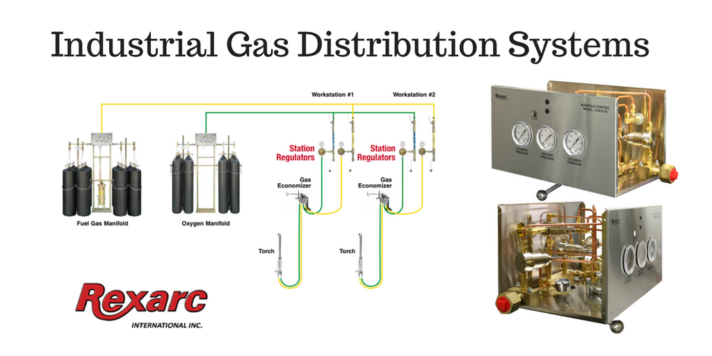
A manifold gas distribution system typically involves the following components in order to distribute molecules from your cylinder bank to the point of use, typically a torch or some other device used for applying gas:
The Switchover
One of the main components of a manifold gas distribution system is the Switchover. Switchovers manually or automatically switch the gas supply from one bank of cylinders to the other enabling one group of cylinders to be changed without experiencing a disruption in gas service.
An automatic controller switches the gas supply to the reserve bank when the gas supply from the primary bank is depleted. The changeover valve setting is reset after the empty cylinders have been replaced and that bank is in reserve. Typically a visual or auditory alarm indicates low pressure in one bank of cylinders while another indicator alerts that the reserve bank is operational.
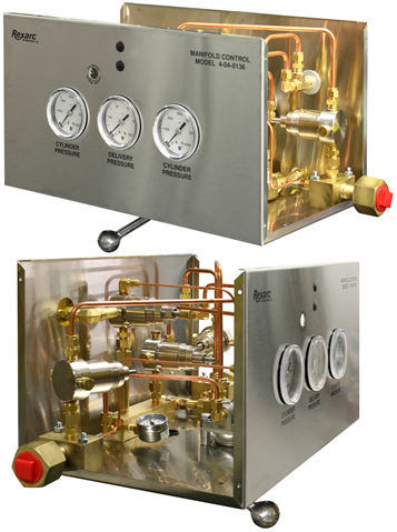
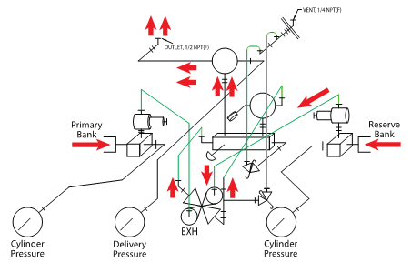
Picture shown is a high pressure switchover without cover
A switchover often includes an intermediate pressure regulator, a line pressure regulator, a changeover pressure switch, an excess pressure relief valve, a pressure gauge for each bank and a pressure gauge that indicates line pressure. Different configurations are used for different gases and different applications.
The position of the 4-way valve indicates which side (or bank) is primary and, therefore, affects the flow path of the gas inside the automatic controller. The switch-over is controlled by the secondary regulator pressure. When primary bank pressure falls below the secondary regulators pressure setting, the reserve bank begins flowing through that regulator.
Cylinders are connected to the manifold header through flexible leads (pigtails) which are rated for the gas type and working pressure requirements. The header valve for each cylinder is typically equipped with a reverse flow check valve.
Flow Data
A switchover is often configured to the flow capacity required by the end user and their various applications. Three major factors are considered when determining the switchover configuration and they are as follows:
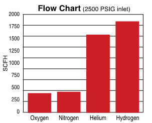
From these three points the switchover will have a max stated flow rate, and each gas being used alters the flow data. For example, lighter gases translate to higher flow rates.
With some gases, there are certain characteristics that need to be considered when figuring flow rates. Acetylene, for example, can only give up 1/10 of cylinder capacity per hour. With CO2 it is not recommended to withdraw more than 35 scfh per cylinder without a heater. Be aware of the properties of the specific gas when determining flow rates.
Manifold System
A manifold system can be a great addition to your facility by increasing safety and improving productivity. Designing a manifold system for correct and safe gas use requires the proper materials to be matched up with flow and pressure characteristics of the application. The switchover box plays a key role in managing the system and enabling your company to avoid downtime while switching out cylinders further improving the productivity and quality of your work.
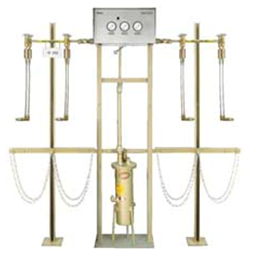
Picture shown is full manifold system for fuel gas service

We are a one stop shop from custom vessel production to full skidding, plumbing and instrumentation.
We stand by our processes and communicate with you on your project status as much or as little as you would like.
We continually reinvest in our people, business, and equipment technology to ship quality products on time.